

Let’s simulate a network using Cisco’s Packet Tracer software, available here. Note Cisco will direct you to enroll in a free networking course to access the software, Cisco courses are excellent but you do not need to complete the course to access the software. Simply sign-up and navigate to section 1.0.3.

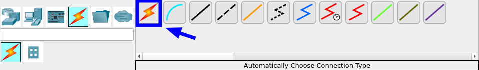
After installation and logging into your Cisco account you’ll see the Packet Tracer interface for the first time. Let’s get you familiar with the interface. Starting with the main toolbar:

Followed by the device selection box which can be controlled on the left using the category and sub-categories. In this example, the “Router” sub-category is selected, therefore the device selection box is showing the different routers.

Creating a Network
Drag in:
- 1 Router
- 1 Switch
- 6 PCs
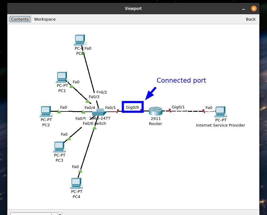
and arrange the devices to match the topology shown below:

In the categories select Automatically Choose Connection Type and connect the devices together:
Configuring the Router
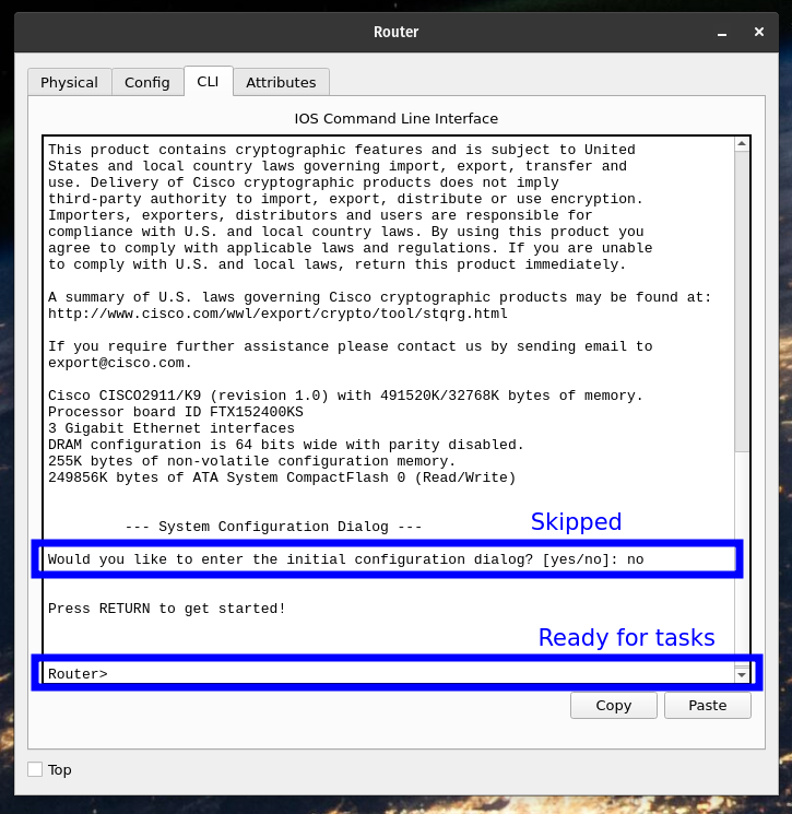
Select the router to reveal the configuration windows and navigate to the CLI (Command-Line Interface) tab. The CLI will prompt initial configuration dialog, just type no and press Enter to skip it.
Use the following commands to enter the configure terminal and select the interface facing the LAN. Afterward, set the IP address for that interface. This will be the gateway for the PCs.
Configure DHCP on the Router
Router>en
Router#conf t
Router(config)#int g0/0

Router(config)#int g0/0 <- The interface facing the LAN
Router(config-if)#ip dhcp pool LAN_POOL <- You can name the DHCP pool anything you'd like
Router(dhcp-config)#network 192.168.1.0 255.255.255.0 <- Specify the network and subnet mask
Router(dhcp-config)#default-router 192.168.1.1 <- The router's IP address within that network (DHCP Reservation)
Router(dhcp-config)#dns-server 9.9.9.9
Router(config)#ex
DHCP will automatically give the clients IP addresses, subnet masks, DNS servers, and default gateway. No need to configure DHCP for the WAN facing interface, instead give the interface a static IP address.
Now for the outside facing interface
Router(config)#int g0/1
Router(config-if)#ip address 192.168.10.1 255.255.255.0
Router(config-if)#no sh
Router(config)#ex

write mem
LAN Client Setup
Let’s confirm the DHCP is working by setting our clients IP configuration up to use it.
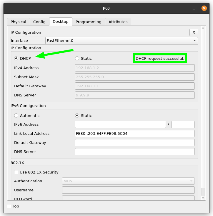
If DHCP fails on the first attempt, set it to static and back to DHCP to try again. After the PCs are connected using DHCP you can validate the configuration on the router by running:
show ip dhcp bindingResult:

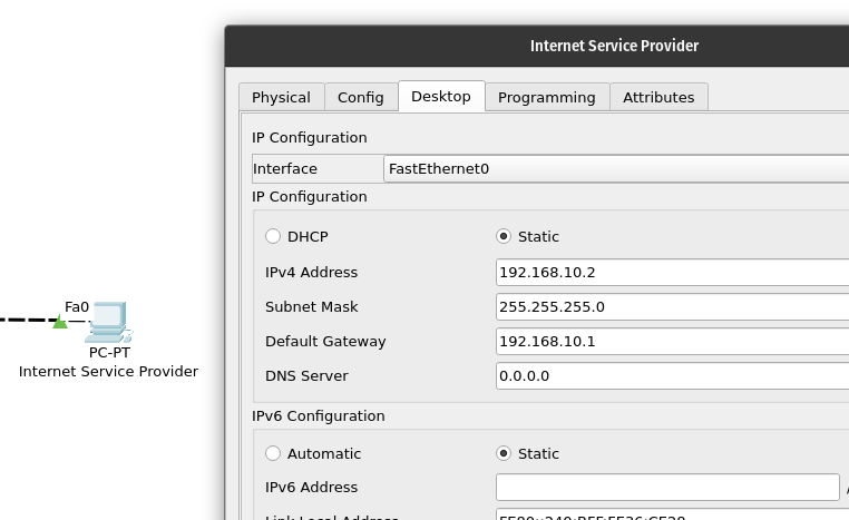
Set the ISP computer’s IP configuration to a static IP address within it’s network.
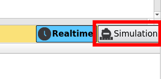
Select Simulation Mode.
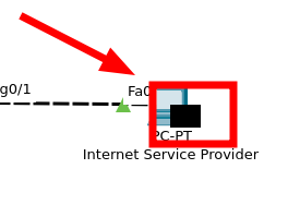
Now select a client PC and open it’s command prompt located in the Desktop tab. Send a ping to the ISP computer to verify proper connectivity. By pressing the next step button in the Simulation Panel you can step the time forward and watch how the switch and router communicate with the other end devices.
Eventually packets should begin to reach the intended destination. You can also view the command prompt window to see the results of the ping operation.

Congrats, you’ve created a network in Cisco Packet Tracer with DHCP.